Just leave the engine at wide open throttle and go through the RPM range by adjusting the braking force. Choose from a full array of products built with heavy-duty components for proven uptime and longevity continuing a tradition of advancing.

Scratch Built Water Brake Questions Answers And Shared Experiences Yourdyno Com Forum
Full-bridge strain-gauge load cell.

. A single absorber unit is made of two stators on either side of a rotor as seen in Fig. Smooth Quiet Control With E-Stop Capability The Positorq Oil Shear Absorber brakes are a unique design for continuous tension control The unique Oil Shear Technology provides extremely smooth ultra quick response negligible wear with no adjustment required high energy Brake Engagement. Through-shaft design allows either end of the dynamometer to be driven and.
Invented by British engineer William Froude in 1877 in response to a request by the Admiralty to produce a machine capable of absorbing and measuring the power of large naval engines water brake absorbers are relatively common today. How to Get More Results Out of Your water brake absorber design. This functions exactly as the name implies and was originally invented in 1877 to measure the power of large naval engines.
Toroidal-flow absorbers couple to engine either via the docking-stations telescoping driveshaft or the mobile-stands heat-treated 1-38x10-spline input shaft and your clutch disk or heavy-duty dampened drive plate. The drawback of water absorbers is their complicated control characteristics making them. 21 Shipped by Email anywhere in the world.
The major advantage of water brake absorbers is that they offer a wide dynamic range meaning one dynamometer can test a wide range of engine speeds and engine torques the SF-902S dynamometer for example is rated for 15000 rpm and up to 1250 lbft of torque however it can also easily test small single cylinder engines that make less than 40 lbft. This type of absorber is widely used in dynamometer testing of various applications due to its relatively inexpensive and power-dense design. We built a water brake years ago but want to build an electro-magnetic eddy current design that is more mobile and compact.
Some are intended to Exhibit providers While Many others are focused on providing an concept. There are 8 coils either side of the stator 16 in total. Each side of the stator is supplied one fluid inlet and outlet totaling four inlets and outlets for the system.
Water Wheel Plan 2. Any other use other then their intent. Plan for 1- 4 foot WaterWheel.
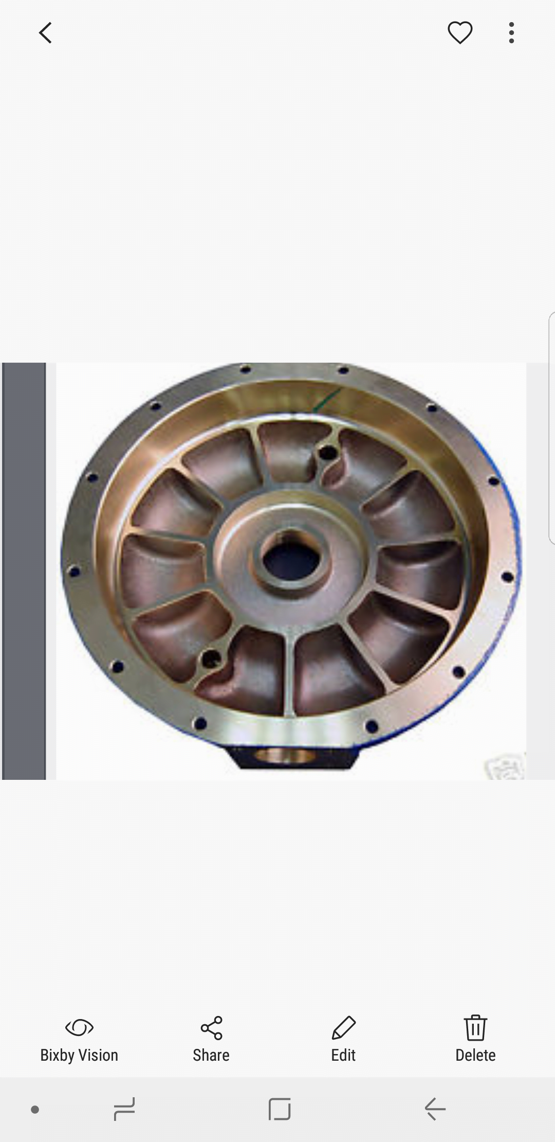
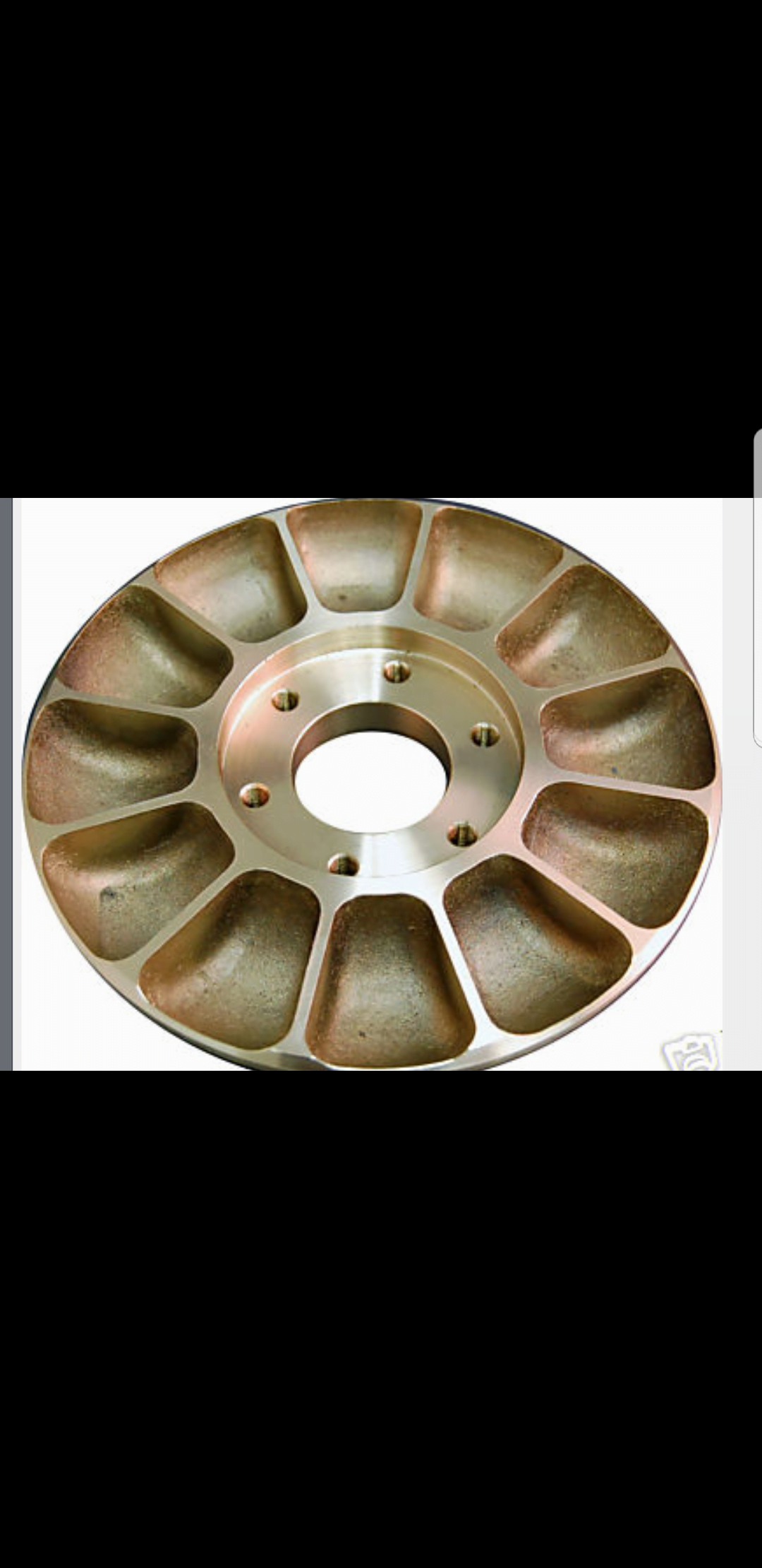
It is no wonder that water brakes are virtually the only choice for testing 2000 horsepower drag car engines. In essence the fluid flow in the two designs are almost identical with the cupped design being more efficient. A water brake is a type of fluid coupling used to absorb mechanical energy and usually consists of a turbine or propeller mounted in an enclosure filled with water.
We have been shopping for a year trying to snag some. The Hall-effect sensor is a Littelfuse Hall-Effect Sensor - 55505 implemented on the driveline and measures up to 7500 rpm. YourDyno can acquire the data during a run and supports both manual and automatic brake control.
Early Superflows did have the open rotor design and are very capable of good results on small engines. I believe how it works is the moving vanes inside the brake are close fitting to the stationary vanes and when water is introduced the fricition starts- more. Need for disassembly of the absorber.
Its fed by a 12 line and the output of the water brake just runs out of the brake onto the floor and goes into a drain. Such applications include the bench testing of motorcycle automotive heavy equipment and even marine engines. The load cell incorporated is an AnyLoad NH-500 S-type that is rated for a capacity of 224 kg.
Most all designs out there are using either the Klam or Telma power absorbers for truck drive lines. As the turbine or propeller turns mechanical energy is transferred to the water due to turbulence and friction. These trunnion-mounted fixed-base Water.
Regardless of the the main target from the brochure is it really should be readable intriguing and functional. Some are built to Display screen expert services While Other folks are centered on providing an idea. Plans shall not be sold copied reproduced distributed shown publicly or.
Incorporated into a water brake engine dynamometer. Brakeabsorber dynos works by braking the engine and measuring the force torque it takes to brake it over the RPM range. To complete the water dynamometer a control system.
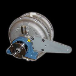
When the lever is moved the curved cam 44 pushes the rearmost stator towards the rotor. Looks to me like the lever is in effect the brake lever. By comparison a 300 pound air-cooled eddy-current absorber with the same continuous power rating is only good to 7000 rpm.
They are noted for their high power capability small. The goal of your brochure may vary from business to small business. The paper investigates the effect of several design parameters of a dynamometer water absorber brake.
Such applications include the bench testing of motorcycle automotive. The water brake absorber is sometimes mistakenly called a hydraulic dynamometer. This design however is more limited in the amount of torque that can be used due to the airs low viscosity Meaning the air has very little flowing resistance.
Load is controlled by varying the level of water in the brake with adjustable inlet andor outlet orifices. Pre-machined mounting plates fit popular GMFord bell-housing patterns may be custom drilled. The shock caused by the acceleration of the water as it passes from pockets in the stator to the pockets.
For the dyno i will wire all the coils together. Building another chassis dynamometer. Power capacity versus size of a water brake is impressive.
Assuming the rotor can float axially on the shaft this decreases the clearance between the rotor and both the front and rear stators thus increasing the. This type of absorber is widely used in dynamometer testing of various applications due to its relatively inexpensive and power-dense design. Equipped with grease-lubricated high-speed bearings.
It doesnt take very much water at all. These are fairly common. The existing system uses two individual absorbers.
Strange Water Brake - Dynamometer. Water Brake Engine Dynamometers - 35X-Series 7350506 35X06 Water Brake Engine Dynamometer Shown. An 8 pound absorber handles over 65 continuous Hp at 12000 RPM.
These pumps typically have one or more vaned rotors spinning in between pocketed stator housings. Water brakes are another form of hydraulic pump absorber. There is a good paper titled Design development of Dynomometer water absorber by Karlis Banis.
Plans will be Emailed to you ASAP after you place your order. For trucking off-road military and mining equipment Taylor Dynamometers water brake dynamometers also known as hydraulic dynos offer the rugged operation and accuracy you need to ensure success. The resistance in each coil is 0945 ohms.
Normally they are operated in 4 stages 2 coils either side for stage 1 4 coils either side for stage 2 so on. The load cell is mounted on the torque arm 01524m 6 in away from the rotational axis of the water brake and is used to. To help YOU to build A water wheel WaterWheel Plan 1.
It is a water brake. 11 Ways to Completely Ruin Your inability to absorb water. HTMLEmbedded Content The goal of your brochure may possibly vary from company to organization.
Scratch Built Water Brake Questions Answers And Shared Experiences Yourdyno Com Forum

Pdf Design Development Of Dynamometer Water Absorber Semantic Scholar
Xs 211 To 1600hp Stuska Dyno

Pdf Design Development Of Dynamometer Water Absorber Semantic Scholar
Scratch Built Water Brake Questions Answers And Shared Experiences Yourdyno Com Forum

Figure 1 From Control Oriented Modeling Of A Water Brake Dynamometer Semantic Scholar

Land Sea Absorbers Water Brake Water Brake Absorbers

Tech Talk Animation On How Water Brakes Work Youtube
0 comments
Post a Comment